
PIC Timer 0
TIMER0 is usually 8 –bit, 16 – bit or 32 – bit and can do the following functions:
- "Speedometer" counts the events when the external input clock (pulses which are counted) by the pin RA4/T0CKI.
- Counts and generated the interrupt or trigger any output of the required time (which can perform by the internal pulses are counted) is the internal clock of the PIC Microcontroller is (system clock divided by 4).
The prescaler can be used by the timer 0 to divide the input by 2, 4, 8, 16, 32, 64, 128, or 256.
Example:
When the prescaler is set to divide by 2, there is 1 output pulse for every 2 pulses which are input to the prescaler.
If set to 256, there will be 1 output pulse for every 256 pulses inputted.
So, the overflow time of TMR0 can be made longer by setting the value of the prescaler.

Prescaler can be configured from bits and T0PS0 T0PS1 and T0PS2 register T0CON. The Prescaler, which is at the center of timer, can be used for either the TMR0 or WDT. The figure above shows the prescaler connected to TMR0.
T
Initializing the OPTION_REG register
The following is an example how we can initialize the OPTION_REG:
PSA=0; // Prescaler is assigned to the Timer0 module
PS0=1; // Prescaler rate bits
PS1=1; // are set to “111”
PS2=1; // which means divide by 256
TOSE=0; // rising edge
TOCS=0; // Internal instruction cycle clock
The PSA bit (bit 3) of the OPTION_REG determines to which of the two the prescaler is connected. The prescaler is a programmable counter whose count ratio is determined by OPTION_REG bits PS0, PS1, PS2. 255(FFh) to 0(00h) an interrupt overflow occurs and T0IF bit (bit 2) of the INTCON register is set (becomes "1").
The hardware is designed such that when both the GIE (bit 7) and TOIE(bit 5) of the INTCON register are Hi ("1") the interruption occurs and the PC goes to address 004h, to start program operation from there. By writing the value of the TIMER 0 register by writing the value in TMR0.
TIMER0 starts to work in 8-bit mode it count from zero to 255 (which is 2^ 8 = 256 8 bit). When timer count reaches the maximum value of 256 the counter will reset and starts counting from zero again.
Some controller has separate TOCON instead of OPTON_REG

TMR0ON: Control bit in the delivery of the interim TIMER0.
T08BIT: bit selection of a working system temporary TIMER0, 8-bit or 16-bit:
T0CS: source selection bit of the time a temporary TIMER0:
T0SE: choose the type of triggering lower edge or upper edge:
PSA: bit choose to use the pre-factor measurement prescaler:
T0PS2; T0PS1; T0PS0: bits choose the value of prescaler.


- TMR0L Register: It will store lower 8 bit value of TIMER0.
- TMR0H Register: It will store Higher (8 bit value if it is 16 bit higher 2 bit if 10 bit) of TIMER0.
PIC Timer 0: Calculation example (INTERNAL CLOCK SOURCE)
Here is an example of the typical calculations for creating an 18ms interrupt repeat rate using PIC Timer 0.
Selecting a prescaler ratio of 1:128 gives the following interrupt period (with Fosc/4(ie. System frequency divide by 4 gives the timer frequency) or 4MHz/4 = 1MHz) and using the maximum overflow from Timer 0.
Calculation:
1/ (1MHz/128/256) = 32.768ms
Formula for calculating time T=
128 – prescaler value
256 – Maximum timer 0 overflow value (2^8 = 256)
//for maximum timer overflow of 256 (ie. 2^8 = 256) it takes 32.768ms time.(ie. Maximum time to generate interrupt)
Obviously this is longer than we need (we require 18ms) but we can cut it down by changing the overflow point (that is by changing the value of 256 it results change in interrupt period).
To do this you need the period of the frequency input to Timer 0 which is(ie. Pulse required for timer to increment the values form 0 -255):
Calculation:
1/ (1MHz/128) = 128us
128us = frequency of pulse that required for timer 0 to increment from 0 to 255
Formula for calculating time T=
128 – prescaler value
This is the period of time to increment from each count (0 - 255) in Timer 0.
256 * 128us = 32.768ms
So by controlling the overflow point you can set the overall interrupt period.
The required period is 18ms so some calculations:
18ms/128us = 140.625 (nearest integer value is 141)
This is the number of counts required after which the interrupt is generated. To use it Timer 0 it is loaded in the following manner:
TMR0 = 256-143; // need 141 but Timer 0 looses 2 at load.
From this point on every 128us is counted by Timer 0 and it will overflow after 141 counts (or 18ms)
Timer 0 overflow time = 141 * 128us = 18ms
PIC Timer 0: Calculation example (IEXTERNAL CLOCK SOURCE)
What is the output frequency - Fout, when the external oscillator is 100kHz and Count=8? Calculation:
First, let’s assume that the frequency division by the Prescaler will be 1:256. Second, let’s set TMR0=0. Thus:

Formula to calculate Fout for Timer0
MikroC Timer 0 Internal Counter Mode
Experimental Setup and SoftwareAfter reviewing the theory, lets think about doing some experiments with the Timer0 module. First, we will create an approximate 1 sec delay using the Timer0 module as a timer. The PIC16F688 runs at 4 MHz clock frequency, so the duration of a machine cycle is 1 μs. To generate 1 sec delay interval, the timer should count 1000000 machine cycles. If we use the prescaler value of 256, the required count will be reduced to 3906. Now, if we preload the TMR0 with 39, it will overflow after 256-39 = 217 counts. This gives the required number of overflows to make 3906 counts = 3906/217 = 18. With this setting, after every 18 overflows of TMR0 register (preloaded with 39), an approximate 1 sec interval is elapsed. The software below implements this to flash an LED with an approximate 1 sec interval.


/*1 sec timer using TIMER0Internal Oscillator @ 4MHz, MCLR Enabled, PWRT Enabled, WDT OFF*/// Define LED connectionsbit LED at RC0_bit;unsigned short Num;// Interrupt service routinevoid interrupt() { Num ++; // Interrupt causes Num to be incremented by 1 if(Num == 18) { LED = ~LED; // Toggle LED every sec Num = 0; } TMR0 = 39; // TMR0 returns to its initial value INTCON.T0IF = 0; // Bit T0IF is cleared so that the interrupt could reoccur}void main() { CMCON0 = 0x07; // Disable Comparators ANSEL = 0x00; // Disable analog channels TRISC = 0x00; // PORTC O/P LED = 0; Num = 0; OPTION_REG = 0x07; // Prescaler (1:256) is assigned to the timer TMR0TMR0 = 39; // Timer T0 counts from 39 to 255
INTCON = 0xA0; // Enable interrupt TMR0 and Global Interrupts do { // You main programs goes here } while(1); // infinite loop}The circuit setup is the same as Flashing an LED. The LED is driven through RC0 pin.
Note: The 1 sec delay that we just created is not very accurate because of the following reasons:
- In this example, the PIC16F688 microcontroller was operated with the 4 MHz internal RC oscillator, which is not highly accurate and stable. For better accuracy, an external crystal oscillator must be used.
- The timer program was written in a high-level language, so we don’t know exactly how the program looked like after being compiled. For an accurate hardware timer, the programming must be done with assembly language, and any instruction that can affect the TMR0 read/write operation, should be accounted as it may introduce additional delay.
MikroC Timer 0 External Counter Mode

The Timer0 module will be used as a counter to count the external clock pulses through RA2/T0CKI pin. The external clock source will be derived from the mains AC supply. The mains AC is 120V, 60 Hz sine wave signal. It will be first stepped down to 9 V, 60 Hz signal using an AC wall adapter. Before applying it to the T0CKI pin, it must be rectified and the peak voltage should be chopped down to +5V. The following circuit will convert the 9 V, 60 Hz AC voltage to an approximate +5 V square wave suitable for the T0CKI input.
The output square wave will be connected to the RA2/T0CKI pin of the PIC microcontroller. The TMR0 will start from 0 and count the incoming pulses for 1 sec. The result will be displayed on the LCD screen. The number of pulses per second is the frequency of the incoming signal, which is 50 Hz. The circuit diagram for the microcontroller and LCD part is shown below.

/*Timer0 as a counterInternal Oscillator @ 4MHz, MCLR Enabled, PWRT Enabled, WDT OFF*/// LCD module connectionssbit LCD_RS at RC4_bit;sbit LCD_EN at RC5_bit;sbit LCD_D4 at RC0_bit;sbit LCD_D5 at RC1_bit;sbit LCD_D6 at RC2_bit;sbit LCD_D7 at RC3_bit;sbit LCD_RS_Direction at TRISC4_bit;sbit LCD_EN_Direction at TRISC5_bit;sbit LCD_D4_Direction at TRISC0_bit;sbit LCD_D5_Direction at TRISC1_bit;sbit LCD_D6_Direction at TRISC2_bit;sbit LCD_D7_Direction at TRISC3_bit;// End LCD module connections// Define Messageschar message1[] = "Frequency= Hz";char *freq = "00";void Display_Freq(unsigned int freq2write) { freq[0] = (freq2write/10)%10 + 48; // Extract tens digit freq[1] = freq2write%10 + 48; // Extract ones digit // Display Frequency on LCD Lcd_Out(1, 11, freq);}void main() { CMCON0 = 0x07; // Disable Comparators ANSEL = 0x00; // Disable analog channels TRISC = 0x00; // PORTC O/P TRISA = 0b00001100; // RA2/T0CKI input, RA3 is I/P only OPTION_REG = 0b00101000; // Prescaler (1:1), TOCS =1 for counter mode Lcd_Init(); // Initialize LCD Lcd_Cmd(_LCD_CLEAR); // CLEAR display Lcd_Cmd(_LCD_CURSOR_OFF); // Cursor off Lcd_Out(1,1,message1); // Write message1 in 1st row do { TMR0=0; Delay_ms(1000); // Delay 1 Sec Display_Freq(TMR0); } while(1); // Infinite loop}The Watch Dog Timer's (WDT)
The function of the watchdog timer (WDT) is to prevent incorrect operation of the software. (Run away: It executes instructions which are not part of the program. / Loop: It executes the same part repeatedly.) The WDT function isn't always necessary. If there is a mistake in the program you can usually recognize there is a malfunction by the way it operates (it doesn't perform the way you expect it to). If the WDT resets the PIC you may not be able to understand what caused the program to malfunction. It may be better not to use the watchdog timer.
To stop the operation of the watchdog timer, reset the WDTE bit of the configuration word (2007h) of the program memory to "0". In PIC (the PICMicro used in this experiment), the watchdog timer has a nominal time-out period of 18 ms, which can be extended up to (18msec x 128 = 2,304msec) by using a prescaler with a division ratio of up to 1:128. The prescaler rate is selected through PS0-PS2 bits of the OPTION register. Note that the PSA bit must also be set to assign the prescaler to WDT, otherwise it will be used by Timer0.

In normal operation, if the watchdog timer is enabled, a WDT reset instruction (CLRWDT) is placed in the main loop of the program, where it would normally be expected to be executed often enough to prevent the WDT overflow. If the program hangs, and the CLRWDT instruction is not executed in time, the program counter is reset to 0000 so that the program restarts.
However, if the PIC microcontroller is in Sleep mode, a WDT time-out will not reset the device, but just causes it to wake up (known as WDT wake-up) and the microcontroller continues program execution from the instruction following the Sleep instruction.
Note: When a Sleep instruction is executed, the watchdog timer is cleared. But the WDT will keep running if it has been enabled. Example: 1
Experimental Setup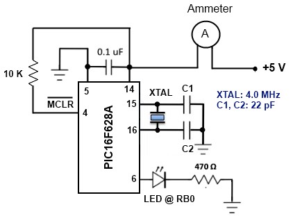 The setup for this experiment would be as shown in the circuit diagram below. The PIC16F628A microcontroller runs at 4.0 MHz clock using an external crystal. An LED is connected to RB0 port pin, which glows for .5 sec after every 4.3 second delay. During the first half of the delay (2.3 sec), the microcontroller is put to Sleep mode and a WDT time-out wakes it up. The remaining 2 sec delay is created through a software routine using NOP instruction. An ammeter is connected in series between the power supply voltage and the microconroller circuit to monitor the current consumption of the circuit. The MCLR pin is pulled high through a 10 K resistor.
Software
The following program is written in C and compiled with mikroC Pro for PIC. The OPTION register is configured to assign prescaler to WDT. The prescaler ratio of 1:128 creates the WDT time-out duration of approximately 2.3 sec. An additional software delay of 2 sec is created using the Delay_ms() library routine. The amount of current consumption during both the delay intervals is displayed on the digital ammeter.
/* Understanding sleep mode in PIC microcontrollers * Test configuration: MCU: PIC16F628A Oscillator: XT, 4.0000 MHz*/sbit LED at RB0_bit; // LED is connected to PORTB.0 void main() {TRISB = 0b00000000;TRISA = 0b00100000;LED = 0;OPTION_REG = 0b00001111; // Assign 1:128 prescaler to WDTdo { asm sleep; // Sleep mode, WDT is cleared, // and time out occurs at Approx. 2.3 Sec // Current is minimum in Sleep mode LED = 1; // After wake-up the LED is turned on Delay_ms(500); LED = 0; asm CLRWDT; // Clear WDT Delay_ms(2000); // Measure current here and compare with Sleep mode }while(1); // current}Example : 2
This example illustrates how the watch-dog timer should not be used. A command used for resetting this timer is intentionally left out in the main program loop, thus enabling the microcontroller to be reset. As a result, the microcontroller will be reset all the time, which is reflected as PORT RB.0~RB.7 LED blinking.
Button S1 and (pull-up) resistance with value of 4.7 K will provide the manual reset mode to the microcontroller.
/* Test configuration:
' MCU: PIC16F628A
' Test.Board: WB-106 Breadboard 2420 dots
' SW: MikroC PRO for PIC 2010 (version v4.15)
' Configuration Word
' Oscillator: INTOSC:I/O on RA.6, I/O on RA.7
' Watchdog Timer: ON
' Power up Timer: Disabled
' Master Clear Enable: Enabled
' Browun Out Detect: Enabled
' Low Voltage Program: Disabled
' Data EE Read Protect: Disabled
' Code Protect: OFF
*/
void main() // Main;
{
OPTION_REG = 0x0E; // Prescaler is assigned to timer wdt
// (1:4[0x0A];1:8[0x0B];1:16[0x0C];1:32[0x0D];
// 1:64[0x0E];1:128[0x0F]);
asm CLRWDT; // Assembly command to reset WDT timer;
TRISB = 0x00; // All port B pins are configured as output;
PORTB = 0x0F; // Initial value of the PORTB register;
Delay_ms(600); // 600ms delay;
PORTB = 0xF0; // PORTA B value different from initial;
while(1); // Endless loop. Program remains here until WDT
// timer reset the microcontroller;
} // End.
nice
ReplyDelete